Mon/Sat 9.00am to 7.00pm


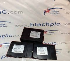
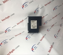
GE IS230TBAOH2C(IS200TBAOH1CCB) Analog Output Terminal Board
GE IS230TBAOH2C(IS200TBAOH1CCB) Analog Output Terminal Board
Brand:
General Electric PLCItem NO.:
IS200TBAOH1CCBOrder(MOQ):
1Payment:
T/TProduct Origin:
USAColor:
Depends on materialShipping Port:
XIAMENLead Time:
IN STOCKWeight:
1000
GE IS200TBAOH1C Analog Output Terminal Board
Description:
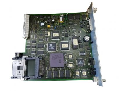
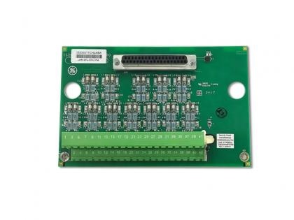
IS200TBAOH1C is designed as GE Analog Output (TBAO) terminal board. IS200TBAOH1C supports 16 analog outputs with a current range of 0-20 mA. Current outputs are generated by the PAOC l/O pack, The outputs have noise suppression circuitry to protect against surge and high-frequencynoise. The TBA( has two barrier-type terminal blocks for customer wiring and six D-type cable connectors.
Driven devices should not exceed a resistance of 900 2 and can be located up to 300 m (984 ft) from the control cabinet, The PAOC contains the D/A converter and drivers that generate the controlled currents. T'he output cuent is measured by the voltage drop across a resistor on the terminal board. Filters reducehigh-frequency noise and suppress surge on each output near the point of signal exit. The following figure displays IS200TBAOH1C in a simplex system.
Q&A:
1. How to install IS200TBAOH1C?
Attach the IS200TBAOH1C to a vertical mounting plate. Connect the wires for the 16 analog outputs directly to the two l/O terminal blocks mounted on the let of the board. Each point can accept two 3.0 mm (#12AWG) wires with 300 V insulation per poinusing spade or ring type lugs. Each block is held down with two screws and has 24 terminals. A shield terminal strip attached to chassis ground is located immediately to the left of cach terminal block. IS200TBAOH1C works with PAOC I/O pack(s) and supports simplex applications only. The l/O pack(s) plug into the D-type connectors and communicate over lONet Ethernet with the Mark Vle controller. Special side mounting brackets support the lO pack(s).
2. How to make a diagniostic test on the IS200TBAOH1C?
Diagnostic tests are made on the terminal board as follows:
• The board provides the voltage drop across a series resistor to indicate the output current. The l/O pack creates a diagnostic alarm (fault) if any one of the eight outputs goes unhealthy.
• Each cable connector on the terminal board has its own lD device that is interrogated by the l/O pack. The lD device is a read-only chip coded with the terminal board serial number, board type, revision number, and the JR, JS, JT connector location. When this chip is read by the l/0 pack and a mismatch is encountered, a hardware incompatibility fault is created.
Related items:
ABB
DAI05
ABB
PM802F
ABB
PM803F
ABB
FI810F
ABB
EI803F
ABB
EI813F
ABB
SA801F
ABB
NDCU-51
ABB
NDCU-51C
ABB
TC514V2
ABB
SDCS-IOB-23
ABB
DI821
ABB
NMBC-01
ABB
07KT97
ABB
07KT93
ABB
TP830
ABB
DSQC601
ABB
DSQC658
ABB
DSDI110AV1
ABB
DSDO115A
ABB
DSPC171
ABB
DSBC170
ABB
DSTC120
ABB
DSDO131
ABB
DSDO110
ABB
DSDP170
ABB
DSSB145
ABB
DSBC176
ABB
DSDP150
ABB
DSAI146
ABB
DSDO115
ABB
DSTD108
ABB
DSSB146
ABB
DSTC121
ABB
DSTA133
ABB
DSTD180
ABB
PM511V08
ABB
DSDI120AV1
ABB
SC510
ABB
SC560
ABB
SDCS-CON-2
ABB
SDCS-CON-4
ABB
AMC-DC
ABB
DSTX170
ABB
07DI92
ABB
DSTD150A
ABB
UA
C389 AE01(HIEE300888R0001)