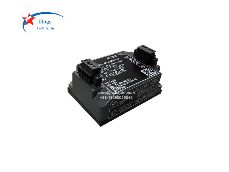
IPC707 244-707-000-012 is designed as a signal conditioner, it has replaced the IPC704 244-704-000-042 since the year of 2019. IPC707 can totally match and even better of the IPC704.
There are below improvements for IPC707:
▪ A new filter compliant with ISO 2954, independent of transmission gain and input impedance
▪ A new grounding concept to improve immunity to rack voltage disturbances
▪ Lower output impedance for long-distance voltage signal transmission
▪ Optional diagnostic circuitry (i.e., Built-In Test Equipment, BITE) that provides continuous feedback on the health of the measurement chain (sensors, cabling, and the IPC707 itself)
▪ For functional safety applications: It meets SIL 2 per IEC 61508, as well as PL c Cat 1 per ISO 13849.
▪ New DIN rail mounting adapter and detachable screw terminal connectors for easier installation.
IPC707 enhance the performace of the IPC704, then how to replace IPC704 to the new upgrade signal conditioner IPC707?
1. Removing the IPC704 Signal Conditioner:
(1) Power off the device completely to ensure safety.
(2) Open the access door or remove the cover of the industrial housing.
(3) Label every wire of the sensor cable (on the "sensor side") and the transmission cable (on the "monitor side," both connected to the IPC704)
(4) On the IPC704, loosen the screw terminals located on the left or bottom of the unit to disconnect the sensor cable from the "sensor side" circuit.
(5) On the IPC704, loosen the screw terminals located on the right or top of the unit to disconnect the transmission cable from the "monitor side" circuit (electronic monitoring system).
(6) Detach the cables from the cable glands (packing gland covers) on the industrial housing.
(7) Remove the IPC704 from its mounting position on the equipment plate or DIN rail.

2. Installing and connecting the IPC707
(1) Make sure the equipment is fully powered down.
(2) Continue using the original industrial housing or fit a new one.
(3) Install the IPC707 into the industrial housing.
(4) Trim or extend the sensor cables and transmission cables to the proper length where required.
(5) Loosen the cable glands on the ABA17x industrial enclosure, then thread the cables through the openings.
(6) Strip about 5 millimetres of insulation from each wire end to expose the inner conductor.
(7) When connecting each wire:
▪ Confirm the corresponding screw terminal and terminal block on the IPC707 for each wire.
▪ Insert the exposed conductor into the designated terminal, then fasten the screw tightly to secure the connection.
3. Configuring the external monitoring system
(1) When swapping IPC704 for IPC707 in CPxxx pressure measurement chains, update all connected external monitoring and protection systems.
(2) Set these systems to apply the standard nominal deviation values of the IPC707
(3) Values represent the diagnostic component (DC) within the IPC707 output signal.











 Mon/Sat 9.00am to 7.00pm