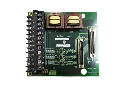
IS200JPDGH1ABC GE IS230JPDGH1A(IS200JPDGH1A)

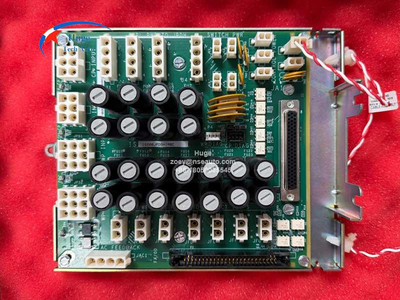
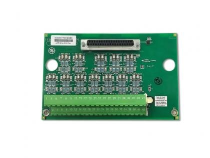
GE Mark VIe DC Power Distribution Board IS200JPDGH1ABC
  • Brand:

    General Electric PLC
  • Item NO.:

    IS200JPDGH1ABC
  • Order(MOQ):

    1
  • Payment:

    T/T
  • Product Origin:

    USA
  • Color:

    Depends on material
  • Shipping Port:

    XIAMEN
  • Lead Time:

    IN STOCK
  • Weight:

    1000
Product Detail
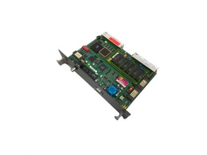
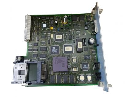
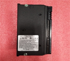
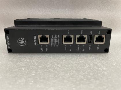
IS200JPDGH1A GE DC Power Distribution Board
Description:
The IS200JPDGH1A functions as a DC power distribution board engineered exclusively for GE Mark VIe industrial control systems, acting as the core power distribution unit to stabilize the entire system’s power supply operation.

The IS200JPDGH1A board delivers two types of DC power: 28V DC control power and switchable 24V / 48V DC wetting power, supplying power to internal control boards, terminal blocks and various system loads. Built-in professional sensing circuits support real-time sensing and fault diagnosis for two external AC distribution channels.

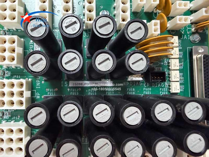
IS200JPDGH1A adopts a redundant dual power input structure with external diodes to boost operational reliability. When paired with a PPDA I/O pack, this Mark VIe power board links to the PDM system and sends real-time voltage feedback signals for timely fault tracking. Every 28V DC output channel comes with fuse overload protection. Moreover, its resistor-centered floating DC wetting power bus enables accurate system ground fault detection, which makes the IS200JPDGH1A an indispensable core power component for complete Mark VIe control systems.

Major Features:
▪ Dual-Type Power Distribution Capacity
▪ Redundant Power Input Design
▪ AC Signal Sensing and Diagnosis Function 
▪ Full Output Protection Mechanism
▪ System Linkage Feedback Function 
▪ Dedicated Floating Wetting Power Bus
▪ Ground Fault Monitoring Capability
▪ Separated Power Supply Load Design 
▪ Multi-Device Power Supply Compatibility

Specifications:

Item

Specification

Rating

28 V dc Control Power Inputs

Two 6-pin Mate-N-Lok connectors for 28

V dc power supply inputs: (JR, JS)

Total bus capacity 40 A max steady state at 55°C (131 °F) /

30 A at 70°C (158 °F)

One 50-pin ribbon cable with diagnostic data from upstream boards (P2)

15 V max

One 4-pin connector for power supply

status contact input (P3)

10 V

28 V dc Control

Power Outputs

Four 4-pin Mate-N-Lok connectors for a

JPDP/JPDH board (J1-J4)

13 A max per pin connector capacity,  10 A slow blow fuse in positive line, typically Bussmann MDA-10

7 A continuous at 70°C (158 °F)

Four 2-pin Mate-N-Lok connectors for

network switch (JC1-JC4)

Fused with self-resetting fuse 1.875 A;

1.5 A continuous at 70°C (158 °F);

2.0 A continuous at 55°C (131 °F)

Five 2-pin Mate-N-Lok connectors for I/O

packs and controller (JD1-JD5)

Fused with self-resetting fuse 0.8 A;

0.5 A continuous at 70°C (158 °F);

0.9 A continuous at 55°C (131 °F)

24/48 V dc Wetting

Power Inputs

Two 9-pin Mate-N-Lok connectors for

24/48 V dc power supply inputs: (JPS1,

JPS2)

Total bus capacity 40 A max steady state, accepts 24 V dc or 48 V dc


One 4-pin connector for power supply

status contact input (P4)

10 V


Impedance to ground from positive and

return line

JP1 jumper in place; 12 kΩ

24/48 V dc wetting

power outputs

Seven 2-pin Mate-N-Lok connectors for a wetting power distribution for contact I/Os board (JFA-JFG)

There is a 15 A fuse in both lines, typically Bussmann ABC-15 or Littelfuse 314015P. The maximum current drawn through each connector must not exceed 10 A at 55°C (131 °F); 8 A at 70°C (158 °F).


One 4-pin Mate-N-Lok connector, 2 channels (JAC1)

Only for sensing feedback, no ac distribution through JPDG board

Vibration Protection

JPDGH1A provides standard Mark VIe circuit board vibration protection rating, and should be used for most

applications

Ambient Rating for Enclosure Design

-40 to 70ºC (-40 to 158 ºF)

Board Dimensions

16.51 cm High x 17.8 cm Wide (6.5 in x 7.0 in)

Mounting

DIN-rail mounting

Base mounted steel bracket


Installation Guide:

1. Cabinet Mounting for JPDG Board
▪ Mount the IS200JPDGH1A vertically on the metal bracket inside the PDM control cabinet via its base frame.
▪ A 50-pin diagnostic connector P2 is located at the bottom of this JPDG power board.
▪ Fasten the module with 4 screws through mounting holes on the top and bottom of the base.
▪ No strict position limits inside the cabinet; install it low down for easier grounding as standard practice.
2. PPDA I/O Pack Installation & Signal Wiring
▪ Plug the PPDA I/O pack into port JA1 on the JPDG board.
▪ Secure the I/O pack to the base with an angle bracket, then lock it using nuts on pre-installed fixing studs.
▪ Run diagnostic feedback signals from other distribution boards to connector P2 with a 50-pin ribbon cable.
3. Power Input Connection Specifications
▪ 28V DC control power: 1 or 2 power inputs via JR & JS connectors, sharing a common 28V DC bus.
▪ 115/230V AC: Only connect to JAC1 for signal sensing & diagnosis; no AC power distribution from this port.
▪ 24V/48V DC wetting power: 1 or 2 inputs via JPS1 & JPS2, sharing a common 24/48V wetting power bus.
IS200JPDGH1AIS200JPDGH1A
Send Us An Inquiry

If you are interested in our products and want to know more details,please leave a message here,we will reply you as soon as we can.

Send Us An Inquiry

Send Us An Inquiry
If you are interested in our products and want to know more details,please leave a message here,we will reply you as soon as we can.

Home

Products

whatsapp